I am still baffled in front of some functionality in Revit families.
One of these is the possibility to create our own justification axis for positioning a beam.
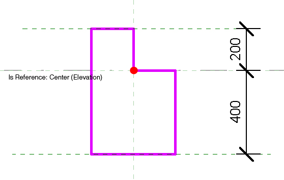
As an example, I design a specific beam, using the “Metric Structural Framing - Beams and Braces” family template.
I draw a little extrusion, and constrain its length. I want have my beam centered on the red dot, so I set the central plane as Reference: Center (Elevation)

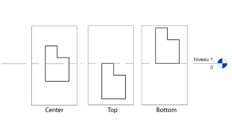
Then I load it into my project and I try different values for the z-direction justification:

As you can see, my beam isn’t centered on the plane set as Reference: Center (Elevation), but keep only its geometrical Top, Center and Bottom as references.
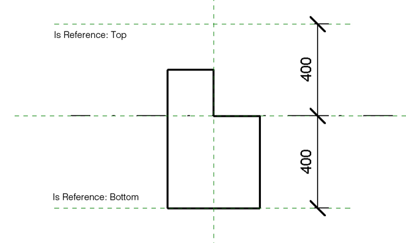
As a workaround, I found out that References Planes can overwrite these geometrical References, but only if they are place outside the geometry. So, I draw two reference planes, I set their References respectively as Top and Bottom, and I place then evenly around the Center Axis of my beam.

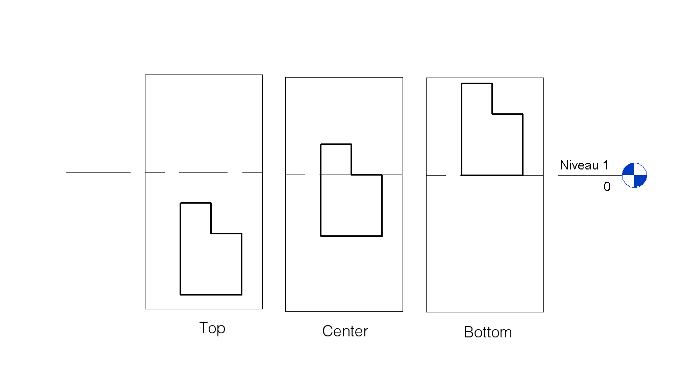
Then, I load it back in project, and test again the z-direction justification of my beam:

OK, it works!
I have also made a lot of trials and mistakes with the different possibilities of these Reference Planes, but I’m still unable to understand some of tricky parts of these functionalities.
And, just in case, if you have any clue where I can find some documentation, please let me know.