I recently have to produce fabrication drawings from a set of panels covering a single curved surface.
These panel were modeled in Rhino 3D, so I decide to extract their boundary curves and use AutoCAD to produce a drawing for every one of them.
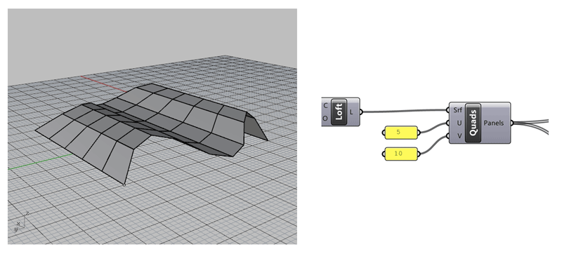
I build here an example by extruding a surface between two symmetrical splines.

This construction method create a single curved surface, which is the easiest to cover with plane panel, here with the “Quad Panels” component from the LunchBox plugin.

Then I extract every panel edge and orient it horizontally on the base XY plane.

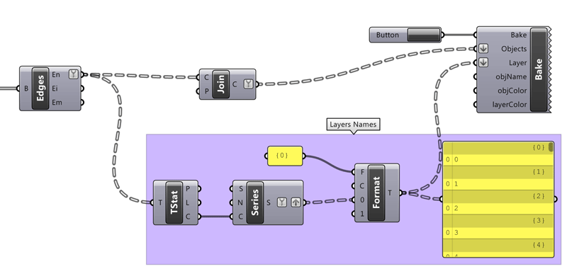
My objective here is to bake every panel boundary curve on a different layer to be able to sort them separately in AutoCAD. To do so, I use the “Object Bake” component from LunchBox. I also use a “Series” to create a layer names for each panel. Here the names are only numbers formatted as text.

The next step is to add dimensions. Sadly, since native grasshopper dimension does not have any output object, we cannot bake them with the “Object Bake”. So I’m using my own Linear Dimension creation component. As you can see, the code is quite straightforward. I use standard Rhino functions to create my dimensions, and have a small private function for selecting or creating the layer to place our dimension.
private void RunScript(bool Bake, Point3d A,
                        Point3d B, Point3d C,
                        string Layer, ref object O)
  {

    if (Bake == true)
    {

      Point3d A0 = new Point3d(A.X, A.Y, 0);
      Point3d B0 = new Point3d(B.X, B.Y, 0);

      double a = (B0.X - A0.X) / (B0.Y - A0.Y);
      double Xc = 1;
      double Yc = Xc / a - A0.X / a + A0.Y;

      Point3d C0 = new Point3d(C.X, C.Y, 0);

      Plane refPlane = new Plane(A0, B0, C0);

      double u,v;
      refPlane.ClosestParameter(A0, out u, out v);
      Point2d A2d = new Point2d(u, v);

      refPlane.ClosestParameter(B0, out u, out v);
      Point2d B2d = new Point2d(u, v);

      refPlane.ClosestParameter(C0, out u, out v);
      Point2d C2d = new Point2d(u, v);

      Rhino.Geometry.LinearDimension dimension =
                  new LinearDimension(refPlane, A2d, B2d, C2d);

      ObjectAttributes dimAtt = new ObjectAttributes();
      dimAtt.LayerIndex = ensureLayer(tag);

      if (Rhino.RhinoDoc.ActiveDoc.
Objects.AddLinearDimension(dimension, dimAtt) != Guid.Empty)
      {
        doc.Views.Redraw();
      }
    }

  }

  // <Custom additional code>
  private int ensureLayer(string lay)
  {
    int i = doc.Layers.Find(lay, true);
    if(i < 0)
      return doc.Layers.Add(lay, Color.Black);
    else
      return i;
  }
With the “Disc” component, I retrieve every summit of my panel boundary, and place a dimension between two of these points. I also use an offset of my panel boundary to set up the position of the dimension line.

Angular dimensions follow more or less the same principle, with two shift to retrieve the point before and the point after a given submit to create our angle measure.

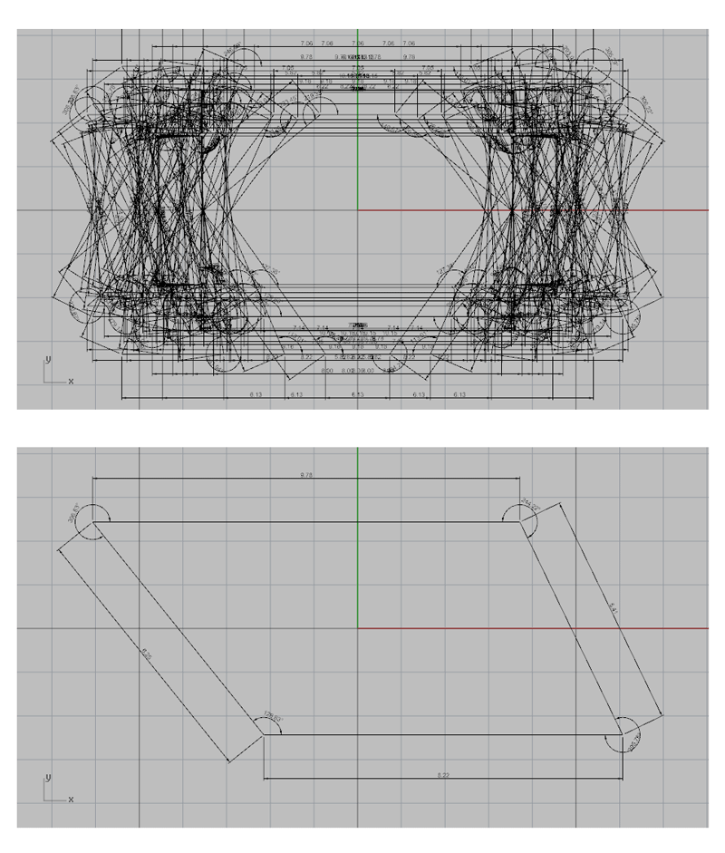
These two dimension components are linked to layer names, so when hitting Bake, each panel curve end up in its layer along with its dimensions. You can see the result below, with every layer displayed and with only one layer visible.

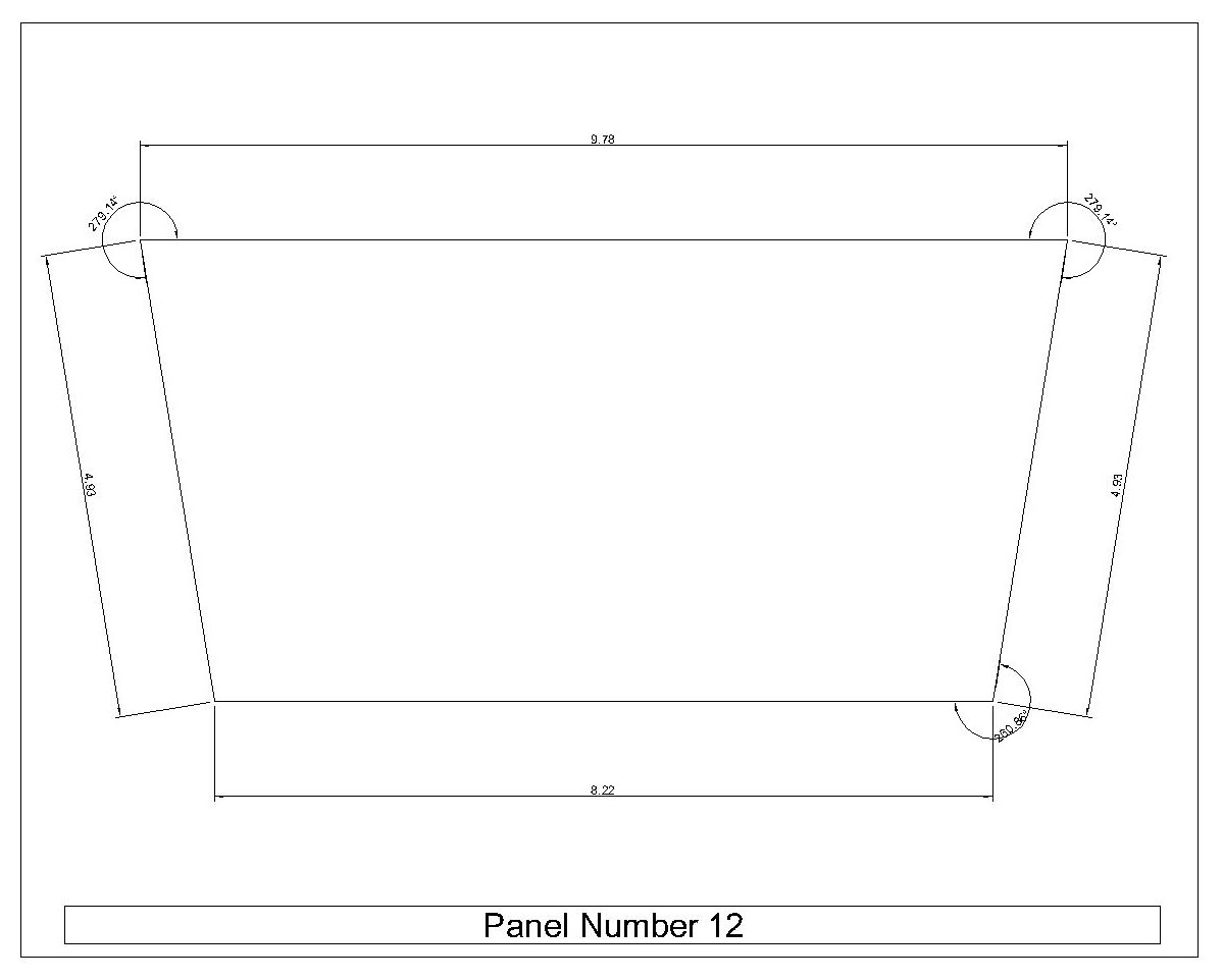
I can now export every curve and its dimensions to a DWG file. This file is edited with an AutoCAD script to paste each layer in a new template file where the titleblock is prepared. It also add the panel number in the titleblock.
