I am not very fond of duct and pipe insulations in Revit. If the concept is very useful, I find difficult to add and edit them. Furthermore, seeing the insulation on every duct and pipe can quickly clutters the view. We want to know how much insulation we have, but we don’t want to see it everywhere.
In a technical drawing, we generally represent insulation only on small parts of the duct, with an annotation, and then infer that the duck is covered everywhere else.
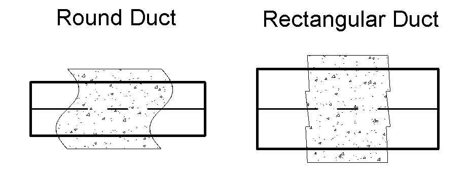
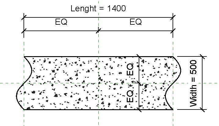
To adapt this method on Revit, I create two detail components, representing the insulation on a round and on a rectangular duct.

This components have a “Width” instance parameter for setting their width regarding the thickness of the insulation.

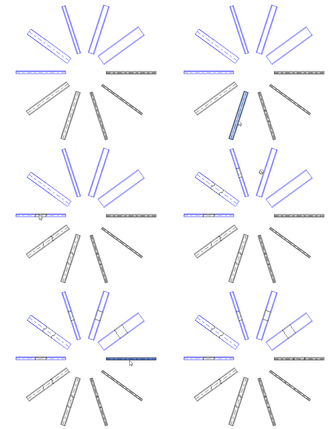
I also create a small piece of code to instantiate these components on selected ducts and pipes.
The idea is to pick a series of duct and pipe, read their insulation thickness, and add a detail component with the corresponding thickness. Like this, we can control where we want to see an insulation, and improve the overall legibility of the drawing.

This solution allow me to create quickly some annotations to represent the insulation without having to display it everywhere. However, this is more a workaround than a real solution. Nothing here is adaptive, and you have to restart the tool each time you edit or even move your duct.
public void InsulationTag()
{
    UIDocument uidoc = this.ActiveUIDocument;
    Document doc = uidoc.Document;

    Reference r = null;

    //Retrive the two symbols
    FamilySymbol rectangularSymbol = null;
    FamilySymbol roundSymbol = null;
    ICollection<Element> collection = new FilteredElementCollector(doc)
        .OfClass(typeof(FamilySymbol))
        .OfCategory(BuiltInCategory.OST_DetailComponents)
        .ToElements();

    foreach (Element element in collection)
    {
        FamilySymbol current = element as FamilySymbol;
        // This NewFamilyInstance overload requires a curve based family
        if (current.Family.Name == "DuctInsulationAnnotationRectangular")
        {
            rectangularSymbol = current;
        }
        else if (current.Family.Name == "DuctInsulationAnnotationRound")
        {
            roundSymbol = current;
        }
    }


    try
    {
        while (true)
        {

            using (Transaction t = new Transaction(doc))
            {
                t.Start("Annotate Insulations");

                r = uidoc.Selection.PickObject(ObjectType.Element, new SelectionFilter(), "Pick a duct");

                if (r != null)
                {
                    MEPCurve mepCurve = doc.GetElement(r.ElementId) as MEPCurve;
                    //doc.ActiveView.GetElementOverrides
                    //Get the middle of the duct
                    LocationCurve locCurve = mepCurve.Location as LocationCurve;
                    XYZ insertionPoint = locCurve.Curve.Evaluate(0.5, true);
                    //Get the angle
                    XYZ vector = locCurve.Curve.GetEndPoint(1) - locCurve.Curve.GetEndPoint(0);
                    double angle = new XYZ(1, 0, 0).AngleTo(vector);

                    //Get the insulation
                    ICollection<ElementId> insulationIds =
                        InsulationLiningBase.GetInsulationIds(doc, r.ElementId);

                    if (insulationIds.Count != 0)
                    {
                        InsulationLiningBase insulation =
                            doc.GetElement(insulationIds.First()) as InsulationLiningBase;

                        if (insulation != null)
                        {
                            FamilySymbol symbol = null;
                            double widht;
                            try
                            {
                                widht = insulation.Width;
                                //Select the detail familly
                                symbol = rectangularSymbol;
                            }
                            catch (Autodesk.Revit.Exceptions.InvalidOperationException)
                            {
                                Parameter outerDiameter =
                                    mepCurve.get_Parameter(BuiltInParameter.RBS_PIPE_OUTER_DIAMETER);
                                if (outerDiameter != null)
                                {
                                    widht = insulation.Thickness * 2 + outerDiameter.AsDouble();
                                }
                                else
                                {
                                    widht = insulation.Diameter;
                                }

                                //Select the detail familly
                                symbol = roundSymbol;
                            }

                            //Create the annotation
                            FamilyInstance annotation =
                                doc.Create.NewFamilyInstance(insertionPoint, symbol, doc.ActiveView);

                            //Change the witdh
                            annotation.GetParameters("Width").First().Set(widht);

                            //rotate the component
                            annotation.Location.Rotate(Line.CreateUnbound(insertionPoint, new XYZ(0, 0, 1)), -angle);
                        }
                    }
                }

                t.Commit();
            }
        }

    }
    catch (Autodesk.Revit.Exceptions.OperationCanceledException)
    {
    }
}

public class SelectionFilter : ISelectionFilter
{
    #region ISelectionFilter Members

    public bool AllowElement(Element elem)
    {

        if (elem.Category.Id.IntegerValue == (int)BuiltInCategory.OST_DuctCurves) return true;
        if (elem.Category.Id.IntegerValue == (int)BuiltInCategory.OST_PipeCurves) return true;

        return false;
    }

    public bool AllowReference(Reference refer, XYZ pos)
    {
        if (refer.ElementReferenceType == ElementReferenceType.REFERENCE_TYPE_NONE) return false;

        if (refer.ElementReferenceType == ElementReferenceType.REFERENCE_TYPE_SURFACE) return true;
        if (refer.ElementReferenceType == ElementReferenceType.REFERENCE_TYPE_LINEAR) return true;

        return false;
    }

    #endregion
}