I came back from the first meeting of the Paris Revit User Group. Julien Benoit give us great insights on how to use Dynamo for data management and Revit automation.
His point of view give me some ideas to feed my current obsession, wall openings.
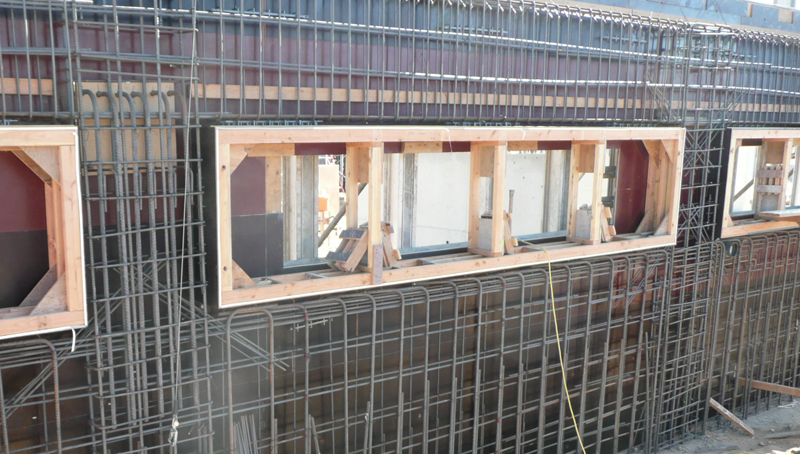
Modeling opening where ducts, pipes, cable trays or conduits intersect walls or floors can be a tedious business. Anyway, it always relies on the same underlining principle: we place a face-base opening family on the wall at the intersection with the duct, the pipe or the cable tray. We also respect a few rules of thumb when placing these openings to keep a structurally sound wall.

There is a handful of plug-in for placing them automatically but they all need a fair amount of work to replace them properly afterward, so I decide to stick to a more “manual” solution.
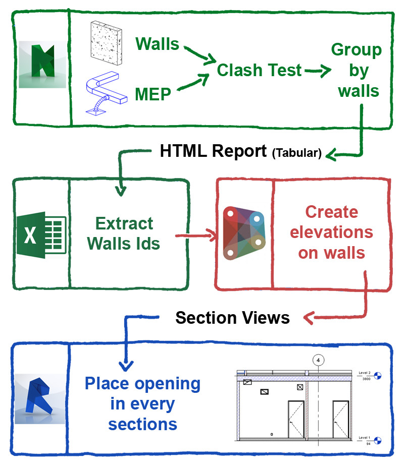
First of all, I use Navisworks to find where I have to place these openings. It gives me a list of walls. Then, I use Dynamo to create an elevation in front of each of these walls. These elevations ease the process for placing the opening family in the concrete model.
The entire process can be sum up like this:

The Dynamo definition use the wall bounding box and normal to create the section view coordinate system. I fumble around with Min and Max points to set the proper crop box for the final view. I also use a few nodes from archi-lab.net package to retrieve walls from their ids. You can find the entire Dynamo definition here.
“A problem well defined is a problem half solved”, and displaying a view of each problem is my first step toward the solution, even if I haven’t find yet any way to automate the entire wall opening thing.