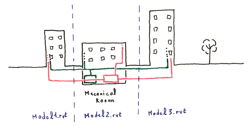
I am currently working on a large building complex, where multiple buildings share the same plumbing and HVAC systems. Every building is linked to a common mechanical room, pipes and ducts run between them.

To address some performance issue, I needed to split this complex into multiple Revit files, one per building, consequently dividing the systems into as many pieces.
But to perform flow and loss calculations, these systems need to be in the same file. More ever, MEP connectors from the linked project are not available in the host project.
However, there is a workaround to be able to display accurate results for calculations that require the entire system to work.
The picture below shows a simple hot tap water supply system, spanning across two files. The water heater is in the host file, and the four lavatories are modeled in a linked project. In this configuration, the system is split in two, and the flow is not properly set up between both files.

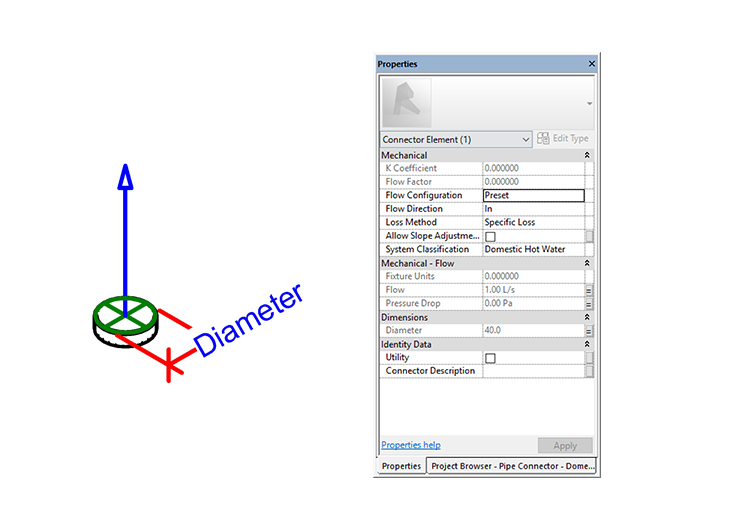
To be able to display the correct flow values on both sides of the system, I create a plumbing fixture placeholder to simulate the rest of the system that isn’t in the file. Autodesk already provides as a part of the standard Revit families four connectors for this kind of emergency. These families are face based, so I create my own, based on the original ones.
This placeholder is a simple plumbing fixture family, with a cylinder shape and a single connector. This connector is set up to be able to define manually every flow and loss values going through the connection.

This plumbing fixture family is placed at the end of the system, on the water heater side. It acts as if the rest of the system, here the four lavatories, were in the host model.
By typing in flow and static pressure values directly in the plumbing fixture placeholder, we end up with the correct values in the host model.

This little workaround allows us to keep accurate system calculation, even with systems split between files.