I am kind of obsessed with wall openings. The entire process of asking a structural engineer for holes in its beloved wall to let ducts and pipes goes through has always been a rather frustrating experience.
After my first article about a semi-automated way for placing an opening family, here is my latest attempt at creating the perfect opening family.
A good opening family must have the following features:
- hosted on a wall, a slab or a beam
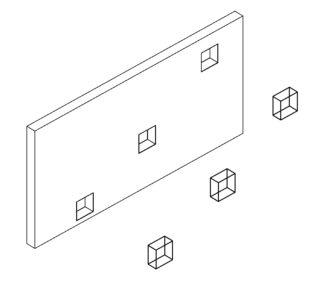
- visible in a 3D view
- fully parametric
- schedulable
- sharable in its own model
- a nice 2D representation
Lets explore these features.
To host them, but still keep the ability to share them in their own model, I use the Generic Model Face Base family template to create my opening family. This template allows me place my opening on any wall, slab or beam, even if they are in a linked model.
In this Generic Model, I create the Opening subcategory, where I will place every element of my opening. This will allow me to fine tune the display of my openings in my model.
I create a bunch of reference planes, and drive them with three shared parameters, Width, Height and Depth. These reference planes help me constrain the Void Form that will cut the host. This void form will create an actual hole in the wall or slab, and will allow me to perform accurate clash detections after integrating these openings.
To be able to see my opening in a 3D view, I draw some Model Lines to outline the general shape of the opening, and place them in the “Opening” subcategory. These Model Lines are only visible in 3D.
The 2D representation is a pretty complex subject, and I have yet to find the perfect solution. After some experiences with Model lines, I have switched to annotations elements. These annotations elements are drawn in two nested families, one for the projection symbol, the other for the cut symbol.
These annotation families are drawn in a Generic Model, with the “Opening” subcategory, in order to follow the same graphical rules than the main family.
I also use Masked Regions to draw filled patterns, and use the Generic Model Override in a plan view to fill them with black. I am not entirely satisfied with this solution, but the workaround involve Detail Items, and I don’t want to deal with two different categories.
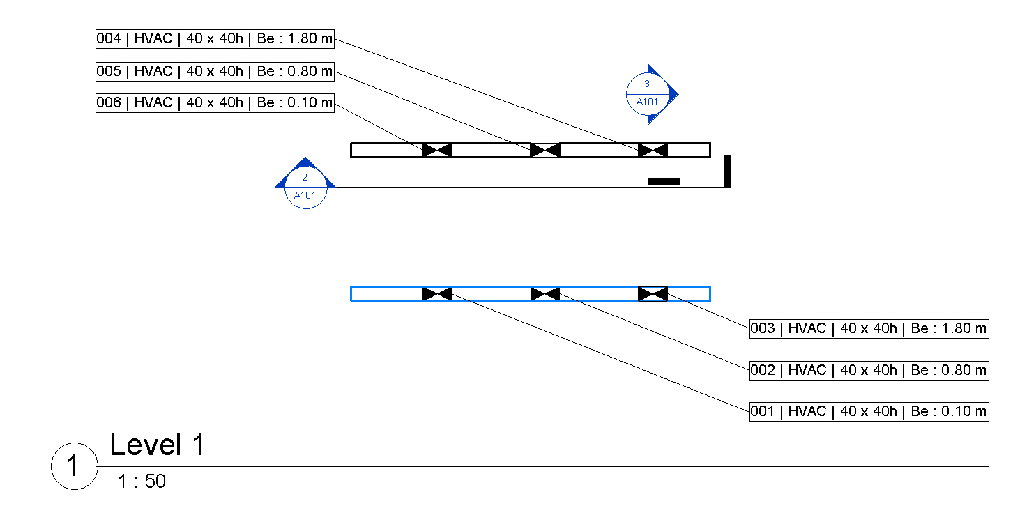
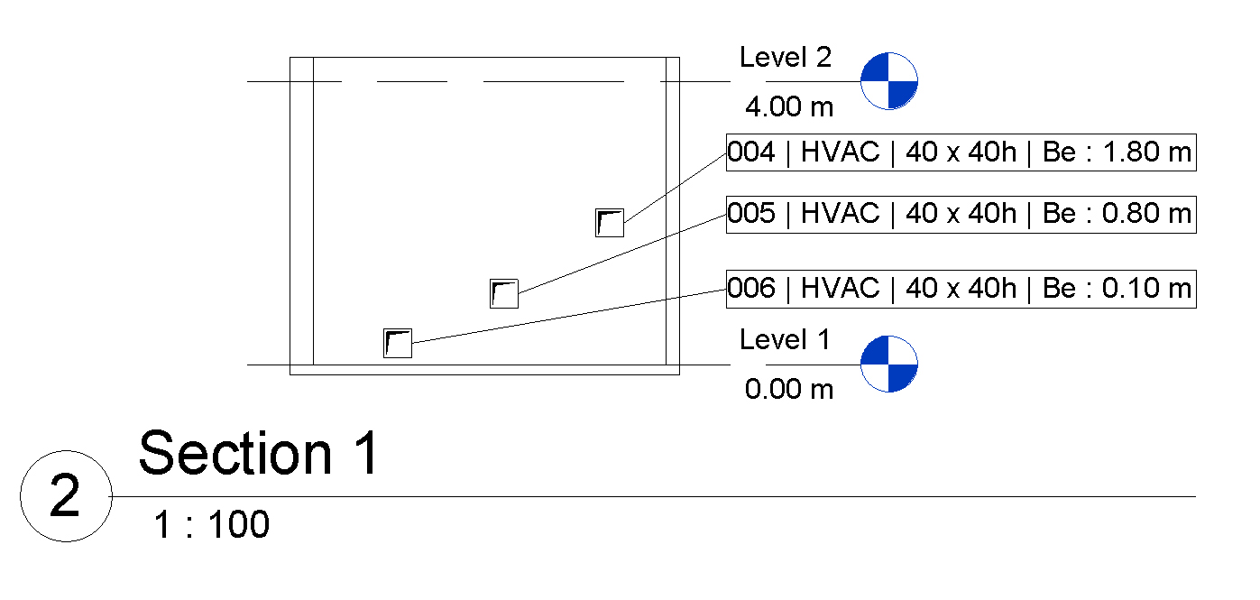
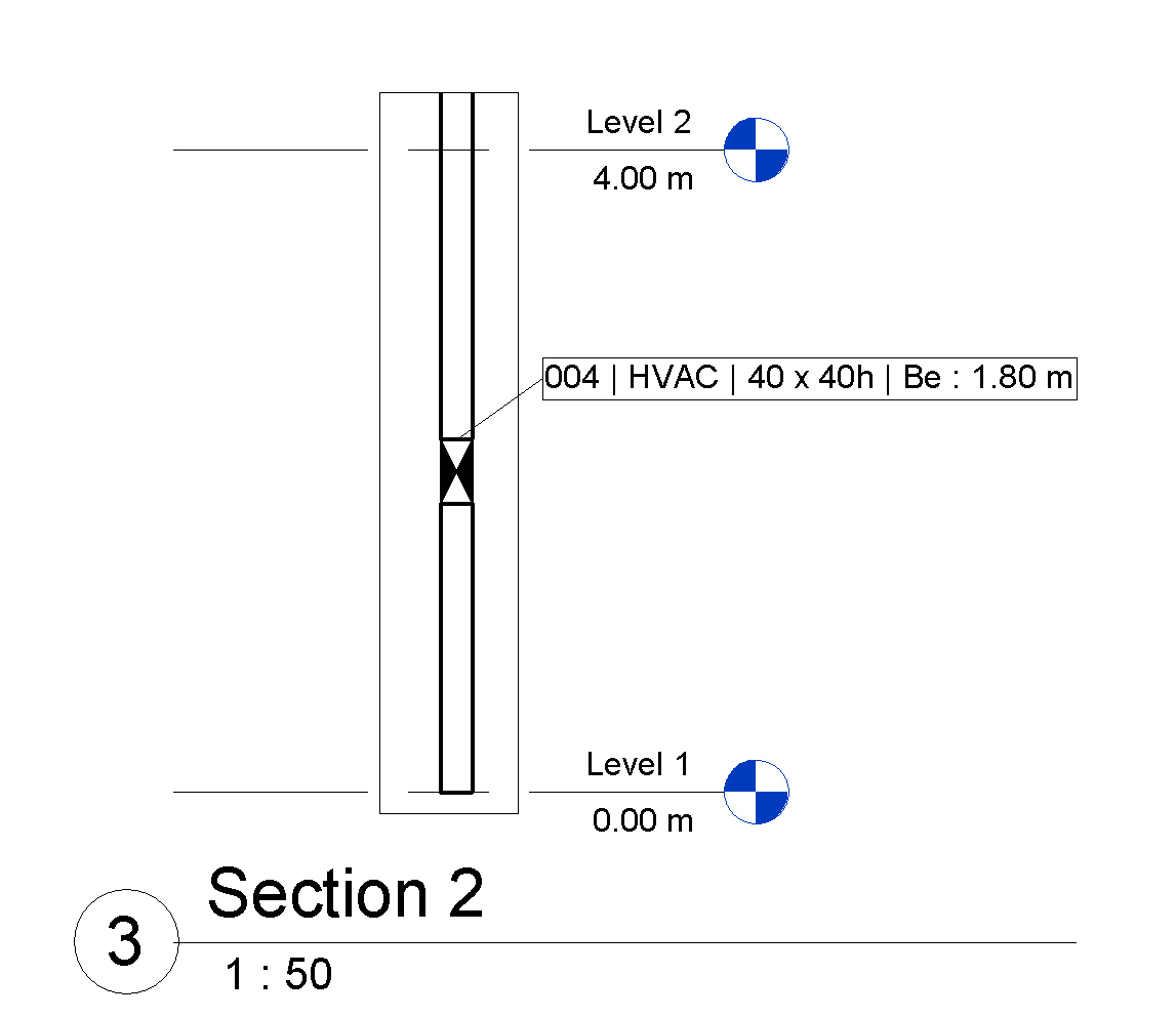
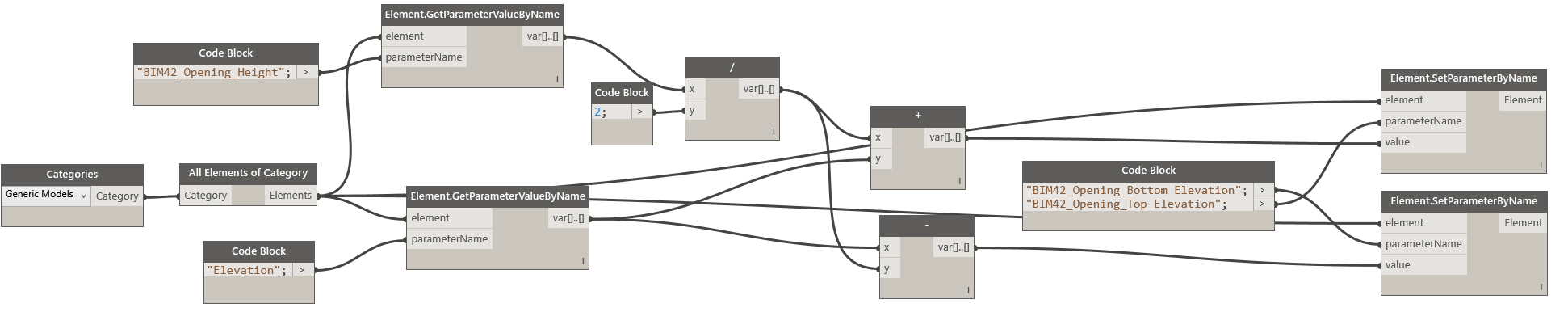
To display the elevation of my opening family in a tag, or a schedule, I create two shared parameter, Top Elevation and Bottom Elevation.
As I was searching for a solution to calculate the elevation, I notice a feature I wasn’t aware of, the “Schedule Level”, present since at least Revit 2015, that allow us to define a reference level. Revit use it to automatically calculate the corresponding elevation. Since this elevation cannot be used directly in a schedule or a tag, I use a Dynamo definition to update elevation values in my shared parameters. This Dynamo definition perform some simple calculation to retrieve Top and Bottom elevations, and send these values in the corresponding shared parameter.
My work with wall openings is far from complete, and subjects like sharing these openings, and managing their modifications are still pending. You will find here the different families, models and Dynamo definition used in this article, feel free to use or improve on them.