One of my colleague is currently working on bridge design with Revit. I have to admit, my first reaction was more like “Revit is not fit for bridge modeling, period”. But after some thought, I found Revit to be a pretty interesting solution to design these kind of infrastructures.
The main issue is that even a simple bridge has a rather complex geometry, with a double-curved alignment and potentially a variable cross section. There is various possibilities to create this kind of geometry in Revit, I will present only one of them here.
This entire article is mostly inspired by the work of Matthias Stark, from Autodesk, and its great AU 2015 class.
The alignment
The first issue we ran into while designing our bridge is the inability for Revit to create a real double-curved, 3D curve.
This is why I create my alignment in Rhino, and use Grasshopper to create a list of X, Y and Z coordinates that define points along my alignment. Another solution is presented by Matthias Stark in his class, where he is using AutoCAD Civil 3D to export the coordinates of the alignment in an Excel spreadsheet.
Once I have all my coordinates in an Excel file, I use a simple definition in Dynamo to create a series of reference points in a Mass family, and use these points to create a curve representing my alignment.
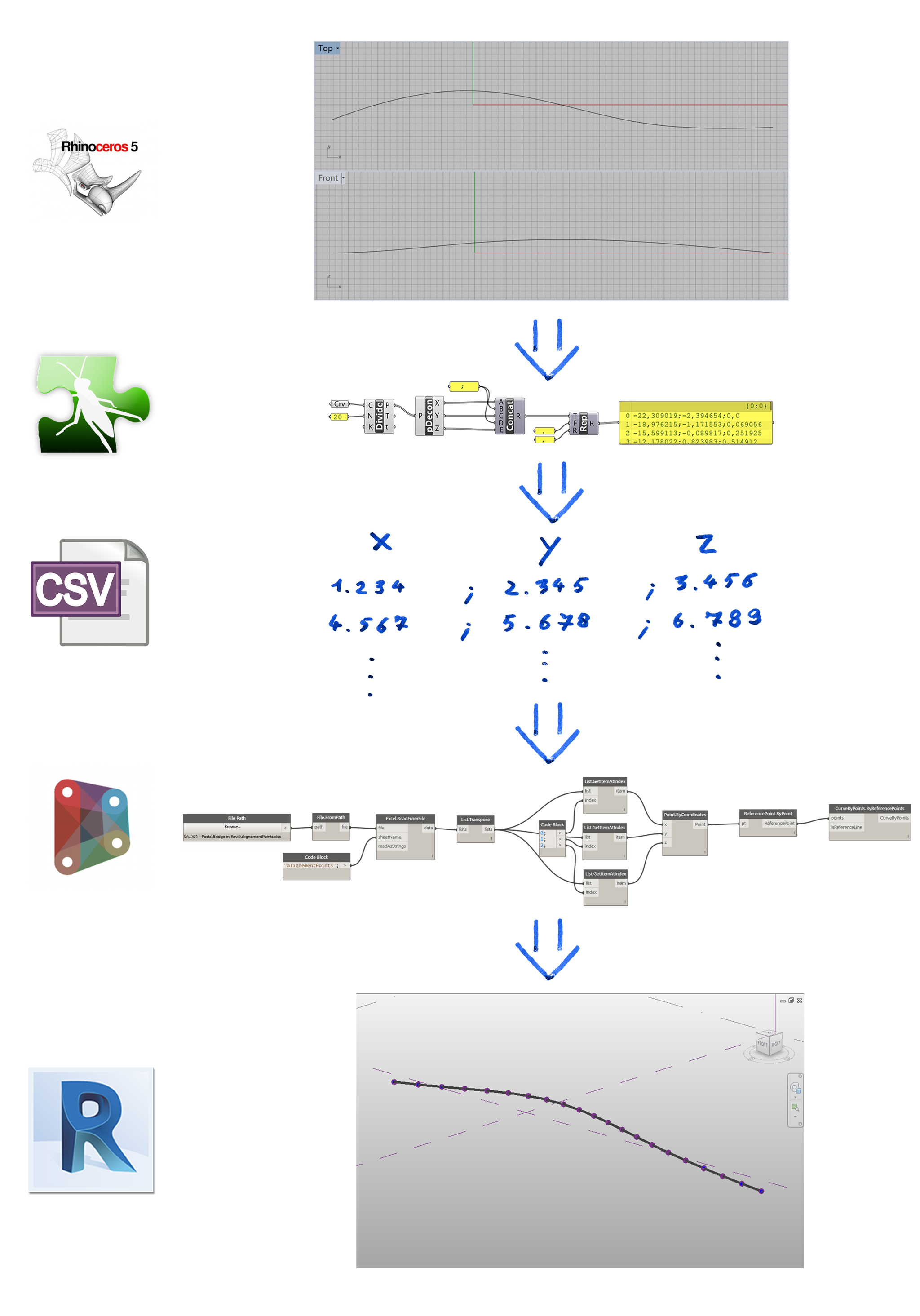
I also make sure that units in my Revit mass family are consistent with the unit of my alignment coordinates points.
The cross section
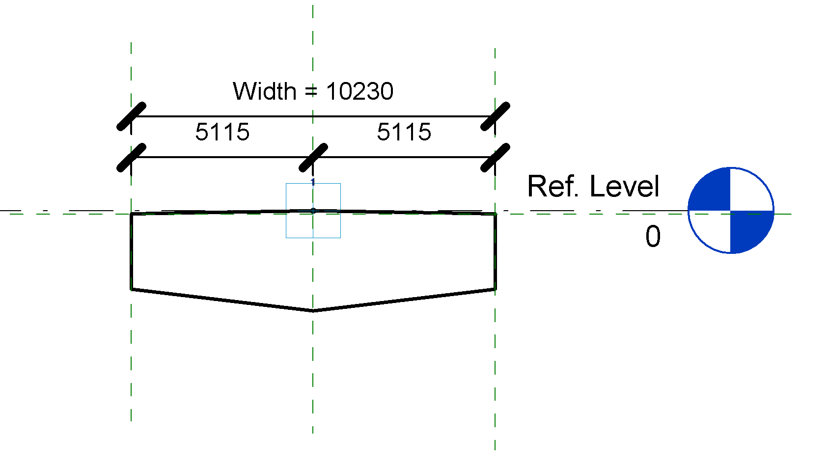
To create the cross section shape of my bridge, I use an adaptive family with a single adaptive point, which will be placed on our alignment.
The keep our cross section properly aligned with our bridge axe, I use the “Orient to” parameter of the adaptive point. By setting it to “Global (z) the Host (xy)”, I make sure than the X and Y axes (Red and Green) will follow my alignment, while the Z axe will stay vertical.
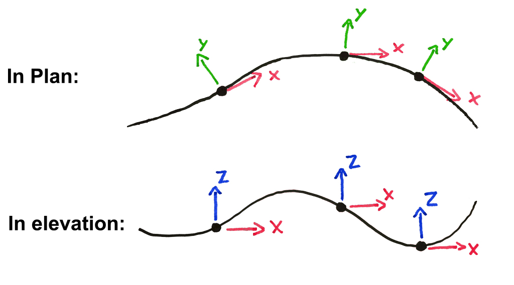 I make a few try before getting it right, but I was finally able to properly align my adaptive component with the divided path. Since the X (Red) axis will be tangent to the alignment, I had to draw my cross section in the “Center (Left/Right)” plane of the adaptive family.
Modeling
The rest of the modeling is pretty straightforward. After placing the first adaptive component on a divided path based on our alignment, just select Repeat to place one on every division point, then decompose the Repeat pattern and create a form.
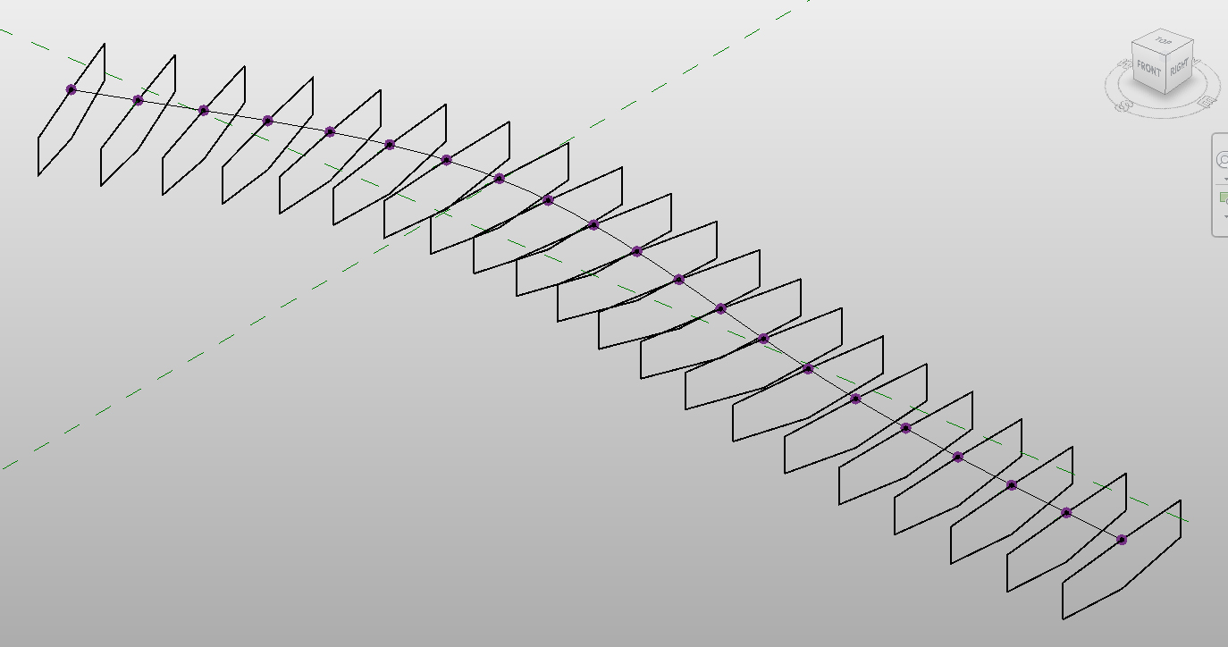
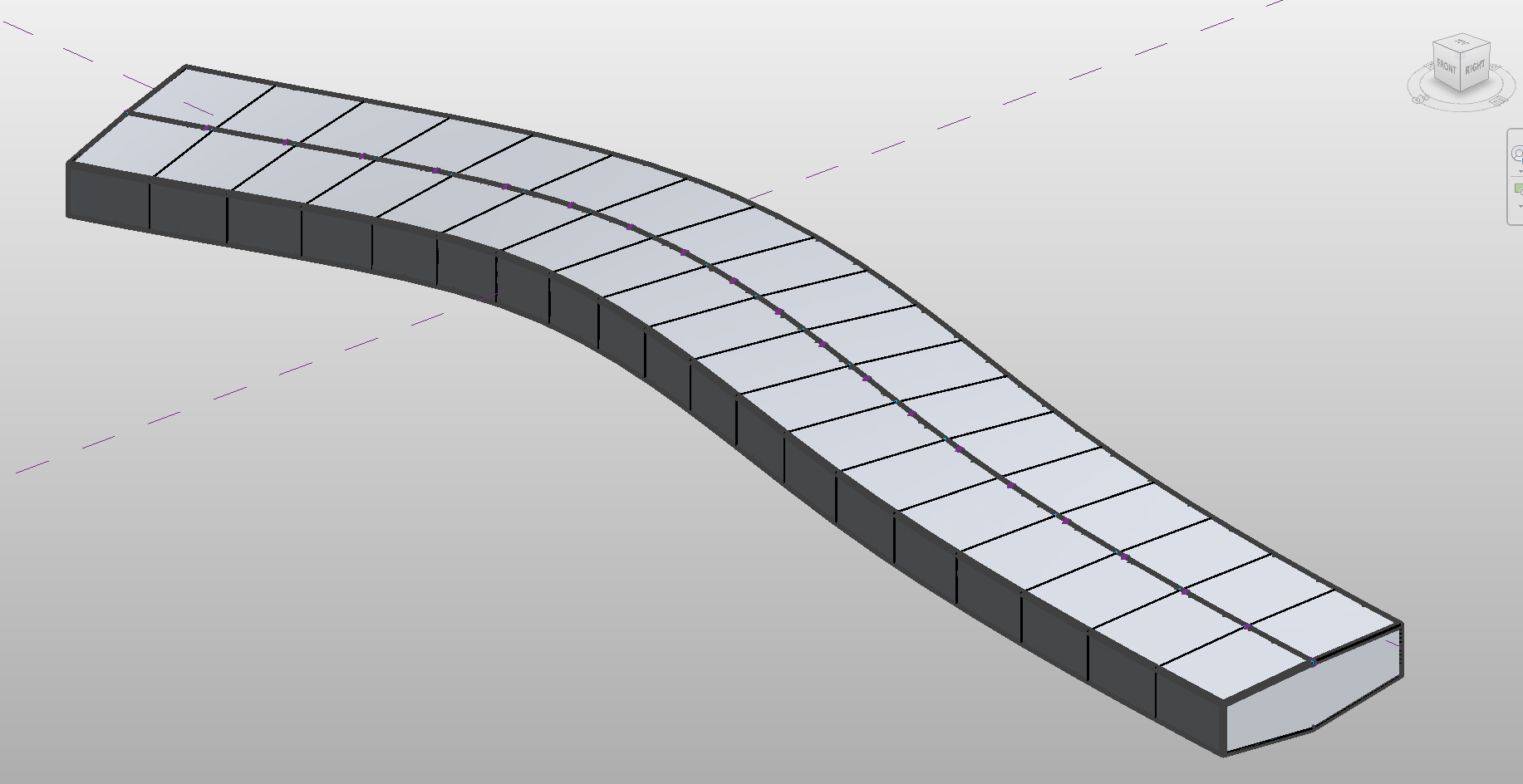
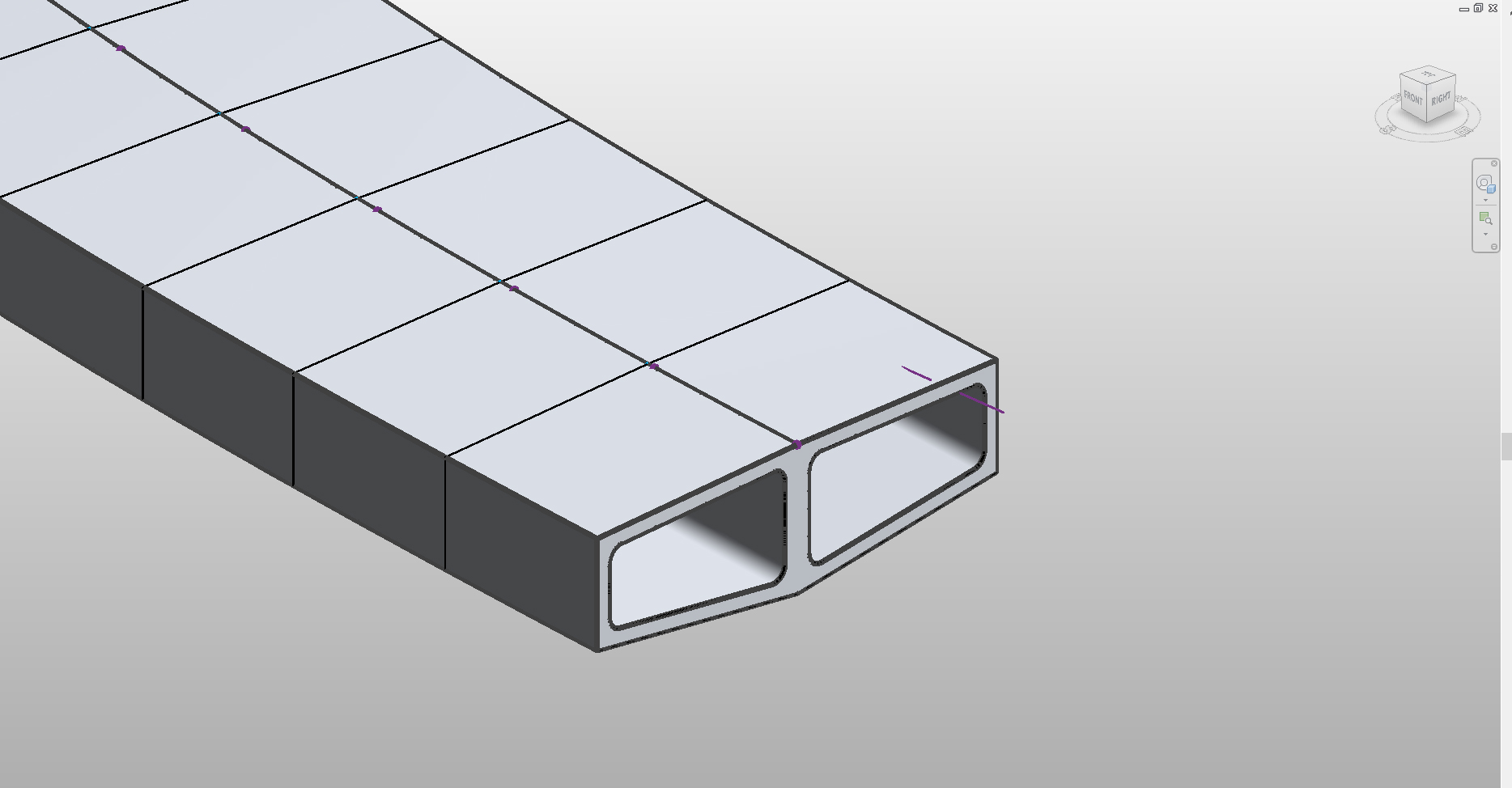
To create the cavity inside the bridge deck, I use the same divided path to place two cavity profiles (right and left) and create two void forms to cut into the bridge deck.
Section View
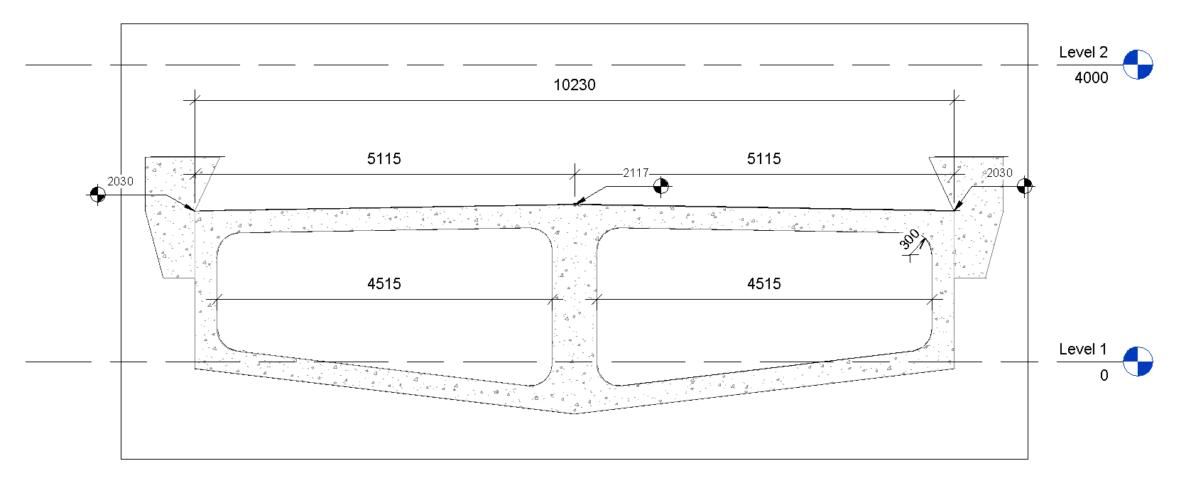
The main issue with this mass family is around dimensions. If you try to add dimensions directly on the Mass family in a section view, these dimensions will be anchored on the wrong point.
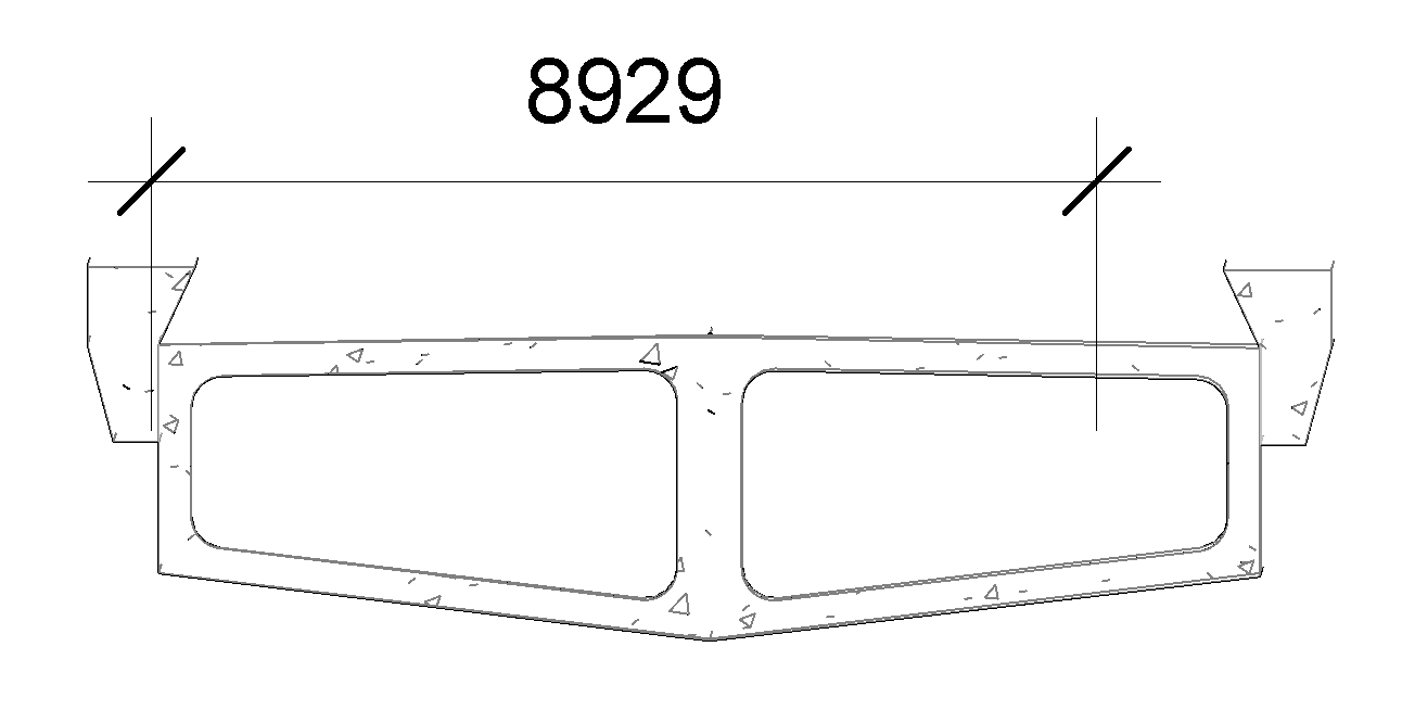
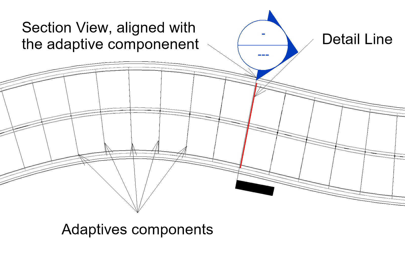
To be able to create section view anyway, I am using the adaptive component loaded in the Mass family. I make it visible in the project and draw a detail line along one of them. This detail line allows me to draw a section view perfectly aligned with my adaptive component
Since my section is perfectly aligned with my profile, it appears in the view and can be used as a reference for the dimensions. I temporary hide my mass family, place the necessary dimensions and show again the mass.
With this workaround, I was able to create a simple section view, with the proper dimensions.
Matthias Stark also present in his class an entire detailing process using Dynamo, and that I still have to explore this part. But his approach to bridge modeling allows me to create a great first draft, and I will keep on digging this solution.