Setting up view range regularly came with great stress, and “why I can’t see this particular element” shouts. To explain it to myself (and maybe other), I write a few lines about it.
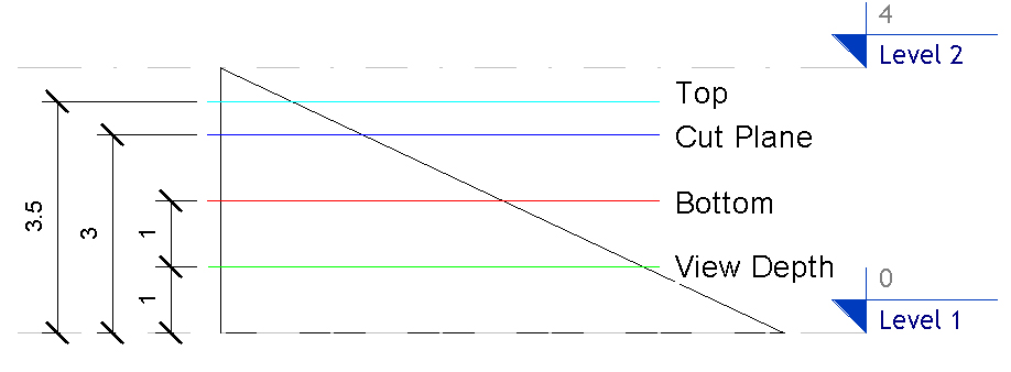
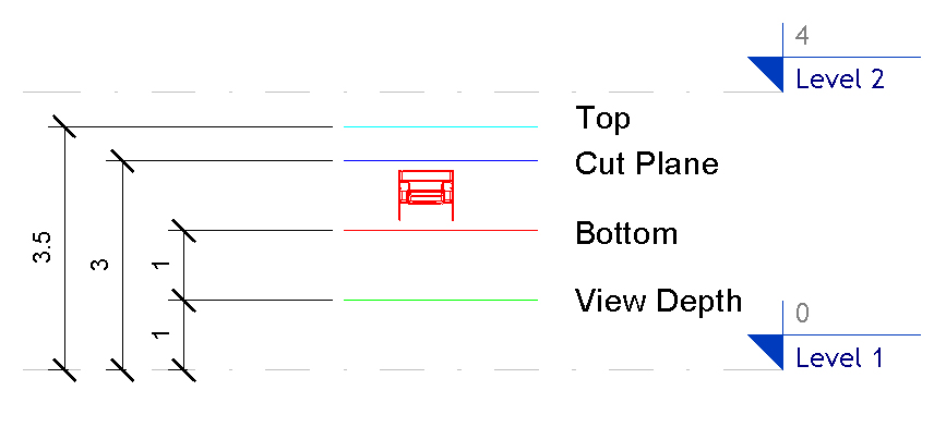
The View Range comes with four elevations, corresponding to the four planes which define a view range:
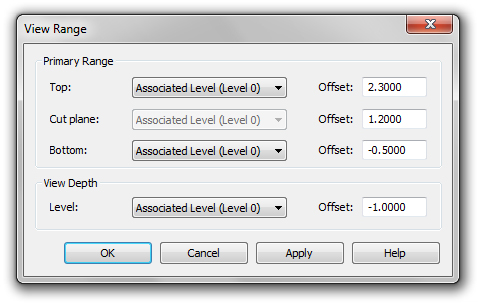
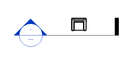
These four planes, draw in a section view:
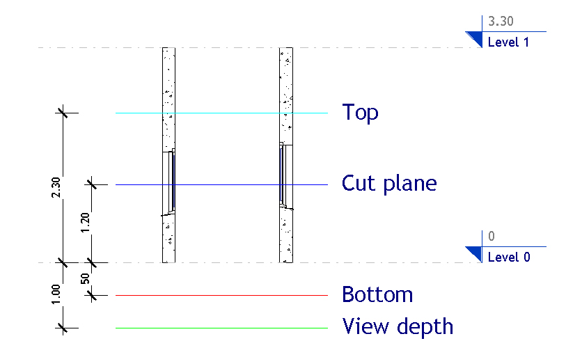
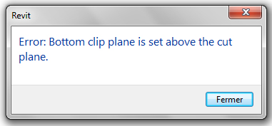
These planes must stay sorted in the same order, i.e., from up to down: Top, Cut Plane, Bottom and View Depth. Trying to change that order will result in this kind of error message:
The general idea behind the view range is that every element between the Cut plane and the View Depth is displayed.
On ceiling plan, where there is only three plans, all objects included between the cut plane and the View Depth plane are visible.
Most objects became entirely visible even if a small part of them is between the cut plane and the View Depth:
Cut by the Cut plane
Above the Cut plane
On the other hand, some families, let’s call them the “cutable” ones, change their appearance when cut by the Cut plane, and display the section display of their material. Cutable objects belongs to one of the following categories: Wall, windows, doors, railings, site, Structural column, Structural foundation, Structural Framing, Structural Stiffener, Casework, Columns, Roof, Ceilling, and Floor.
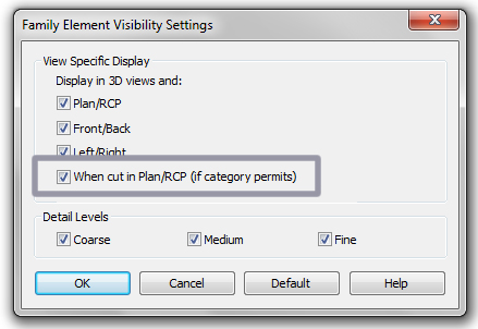
In case of an editable cutable family, each geometric element composing this family can be hidden when cut by the Cut plane:
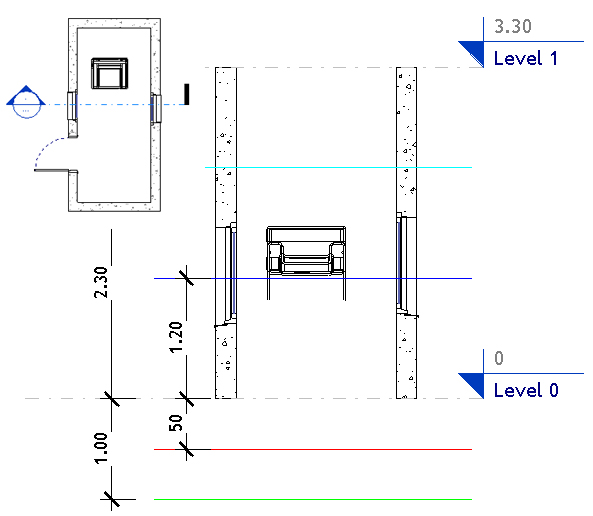
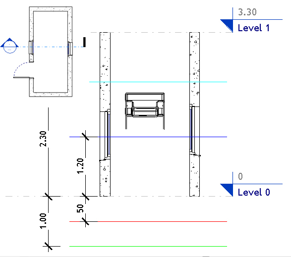
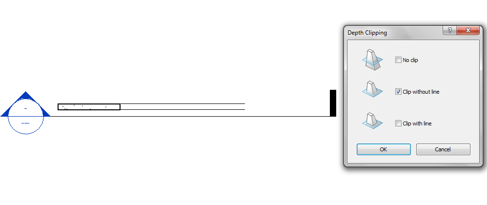
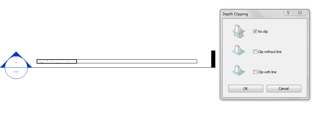
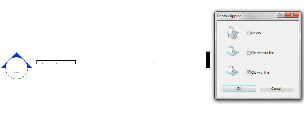
If the View Depth setting is set to Clip (With or without line) these objects are also cut by the View Depth Plane. For example, with a wall with an edited profile:
The corresponding view plan, with different Depth Clipping:
Some categories have also specific behaviors. For example, a windows stay visible above the cut plane if the hosting wall is still below the cut plane.
I also note than an Object Syle or an Override does not apply to an object placed below the Bottom plane, or above the top plane for ceiling view. For example, if Furniture Object Style is set to Red, a chair is normally displayed in red in a plan view:
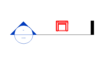
But when the same chair is placed below the Bottom plane, it become black:

Filters Override, on the contrary, stays active whenever the object is bellow or above the Bottom plane. I don’t know the reason of such behavior, maybe someone from Autodesk could be able to answer.
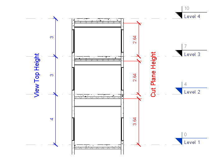
Finally, to help users with this view range issues, I create a general section of the building with two different set of dimensions, one for Top height, the other for Cut Plane Height. This section is printed and used as a handout for Revit users to set up themselves their view range on their working views.
EDIT : I have found on Augi the solution for objects placed below the Bottom plane. These elements are displayed with the project’s